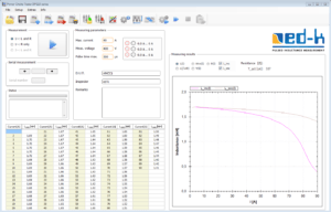
A PC is used to operate and display results from the Power Choke Tester DPG10 via a new developed simple and intuitive graphical user interface. The measuring instrument can be connected to the USB port or the RS232 port of the PC.
The following parameters can be set before measuring inductance:
- Maximum current: The measuring impulse is terminated when this value is reached, so long as the pre-set maximum duration of the measuring impulse has not been reached before.
- Measuring impulse voltage: A value should be entered here that corresponds to the test specimen’s voltage levels during normal operating conditions.
- Maximum duration of the measuring impulse: The measuring impulse is terminated when this value is reached, so long as the maximum current level is not reached before.
All settings can be saved and reloaded when required. This considerably eases conducting a series of measurements for quality control checks during production.
If the instrument is incorrectly used (e.g. incorrectly connected or setup), then detailed error warnings help to quickly solve any problems.
After the measurements are complete, the results L(i) are displayed in the form of both a diagram and in a table. Alternatively in some cases it could be useful to display the inductance as a function of the voltagetime-integral ∫U(t)dt applied to the inductor. The display mode is togglable.
A resistance test is automatically carried out before every inductance measurement is undertaken because the ohmic portion of the inductor must be considered in the calculation of the inductance curve. A resistance test can also be carried out separately.
The PC software for the Power Choke Tester DPG10 is subject to continuous improvement and contains a lot of additional functions, e.g.
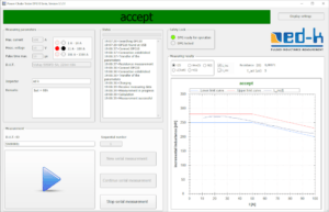
- Definition of limit curves for automatic pass/fail testing
- Functions for ease of routine testing
- Comparison of different measurement curves in one diagram
- Data export and import (XML, CSV)
- Automation of the measuring process for serial measurements using InterfaceBox
- A comprehensive and well-documented SDK is available for developing your own evaluation software
- Demo VIs for data acquisition in LabVIEW
Current information on new software features can be found further down on this page.
Routine Testing in Mass Production
Since software version V3.5.x, two different applications for operating the Power Choke Tester DPG series with different user interfaces have been included in the scope of delivery.
- Laboratory application: an application intended for laboratory operation and small series testing with the already known user interface
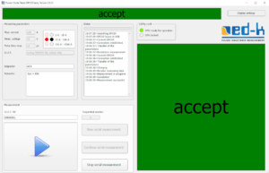
- Production application: an application optimized for routine testing in mass production with a user interface reduced to the necessary operating elements and a configurable large display
In the production application, the measurement results are saved in a database. It enables very effective and fast routine testing in mass production, even by unskilled personnel. When using a scanner, no actions are required by the user other than connecting the test object. If connecting is automated, a fully automatic test is also possible.
In the laboratory application, the data can be saved either in XML files as before or in a database.
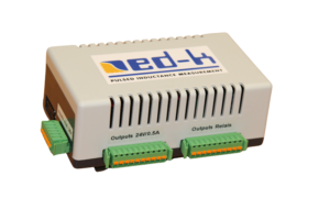
With the help of our new InterfaceBox INT1, inductance measurement is possible in a fully automated test line without having to write your own software to control the Power Choke Tester DPG10. It provides the interface between our PC software and a fully automated test line.
Since version 3.6.x, the software is only available as a 64-bit application. Customers who require the laboratory application in 32-bit can use version 3.5.104.
Current functional enhancements
Software version 3.7
- New L3_diff-measurement diagram for 3-phase inductance measurement
Software version 3.6
- Development of the new programming interface ‚edkAPI.dll‘ for integrating measurements into your own software solutions, including sample code in C#, VB.NET, C++ and LabVIEW
- Integration of the InterfaceBox to control the Power Choke Tester DPG10 in a fully automated test line
- Much more extensive settings dialog
