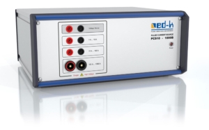
Pulse Current Source PCS10-1000B
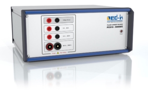
Pulse Current Source PCS-3000B/E
There are two models of the pulse current source available. The model type PCS-1000B with up to 1000 A pulse current and the model type PCS-3000B/E with up to 3000 A pulse current.
The Pulse Current Source PCS10 series is suitable for inductive and resistive loads. The pulse energy is taken from a capacitor battery and can be up to 2kJ depending on the model, pulse repetition rate and selected pulse voltage. Both the pulse duration and the current can be preselected as criteria for ending the voltage pulse.
The voltage and current are unregulated. When the pulse energy is relatively small compared to the energy stored in the capacitor bank, the pulse voltage is approximately constant. The pulse width can be set between 3µs and 130ms in increments of 500ns. The maximum current, upon reaching which the pulse is terminated, can be set in steps of 1A.
The output voltage pulse is triggered by a command via USB or RS232 interface. All pulse parameters like voltage, maximum current and maximum pulse width are also set via commands. After the end of the pulse, the maximum current that has flowed is reported back.
The communication protocol is described in the operating instructions so that the control can be easily implemented using your own applications. Example projects in C#, C++ and VB, which can serve as a basis for own applications, are included in the software package.
The PCS10 series has two fiber optic trigger outputs and one TTL trigger output. These outputs can be used to control external devices or drivers for power transistors. The trigger outputs are set when the power output is turned on and are reset again when the power output is turned off. However, both the rising edges and the falling edges of the trigger signal can be delayed in relation to the edges of the power output using appropriate software commands, e.g. to compensate for the signal delay of a driver. On the rising edge, the delay can be set up to 8.75µs in 438ns increments. On the falling edge, the delay can be set up to 3.75ms in 188ns increments. If the delay is set to 0, the trigger signals change level a few µs before the power output.
The devices can also carry out a continuity and a leakage test. Via a constant current of 1mA or 10mA (limited to 10V) can be checked whether a connected load, e.g. a power transistor, has broken down.
Applications are e.g. the test of power semiconductors (RBSOA, SCSOA), many other applications are possible.
Scope of delivery
- PCS10 – 1000B or PCS10 -3000B/E basic device
- Cable set
- Connection line 2x Force, 1x Sense, 0.6 m each with alligator clips
- USB cable and RS232 cable
- Power cord
- PC software for Windows
- Instruction manual
- Communication protocol for integration of the instrument into automated test environments using your own applications
- Hard-top case (CASE1)
- Customer specific connection lines on request


